Introduction:
Some projects nag at you for years. This is one of them. About three years ago I transplanted an ESP32 into the cheap-and-cheerful dehumidifier that keeps our conservatory habitable, wired a relay across its ON/OFF button, and called it “smart”. The trouble was it could press the button but it never really knew whether the thing was actually running. I’d hung two wires off a front-panel LED and tried to read it with the ESP’s ADC, and for three years that reading was, to put it kindly, a work of fiction.
This summer I finally got to the bottom of it – and the fix turned out to be far more satisfying than the bodge it replaced. Instead of squinting at one LED, the ESP32 now quietly listens to the little serial bus that drives the whole display, and reads every lamp, the humidity digits and the button presses straight off the wire. Here’s how it went.
1. The patient
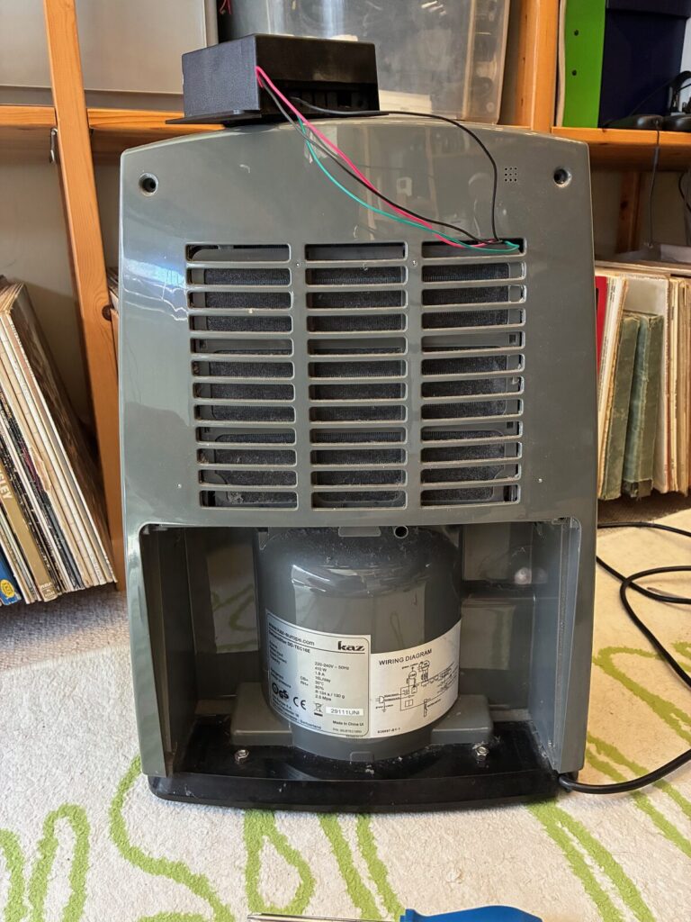
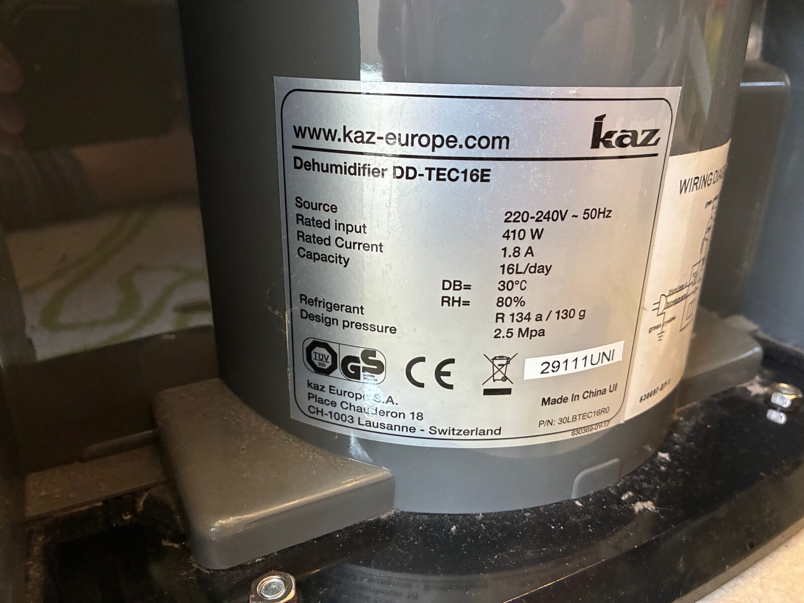
The unit is a Kaz DD-TEC16E – 220–240 V, 410 W, R134a, a claimed 16 litres a day. Nothing exotic: a compressor, a two-speed fan, a tank with a float switch, and a small display board with a 2-digit readout and a row of indicator LEDs (Run, Water Full, Defrost, Timer, Hi, Lo).
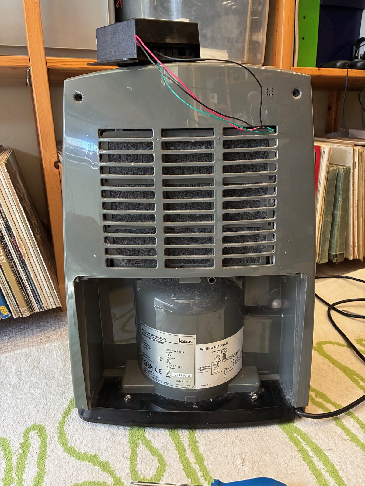
The goal in Home Assistant was modest on paper: a reliable running / tank-full / defrost state, the humidity reading, and full button control. The relay-across-the-button already handled “off and on again”. Everything else hinged on that one honest question I’d never been able to answer – is it running right now?
2. Why the old approach never worked
The penny finally dropped when I looked properly at where my two sense wires actually went. They were both sitting across one LED – the “RUN” lamp – and that lamp isn’t a simple on/off light. It’s part of a multiplexed display: a driver chip strobes the LEDs and the 7-segment digits dozens of times a second so that, to the eye, they look steadily lit. To an ADC, that pin is a permanent blur of scan pulses in every single state, running or not. No amount of averaging, peak-holding or clever “quiet period” detection was ever going to pull on/off out of it, because the traffic is always there. Three years of filtering a signal that fundamentally didn’t contain the answer. Ah well – live and learn.
If the display is multiplexed, though, then somewhere there’s a bus carrying the real state of every lamp and digit. Find that, and you don’t need to guess at LEDs at all.
3. Meet the TM1618
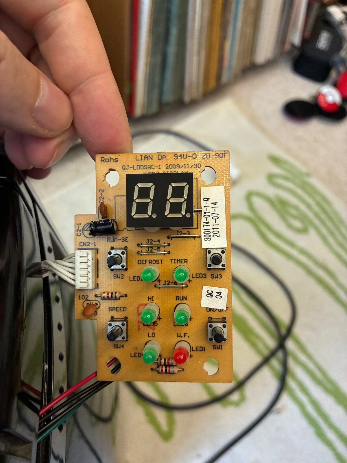
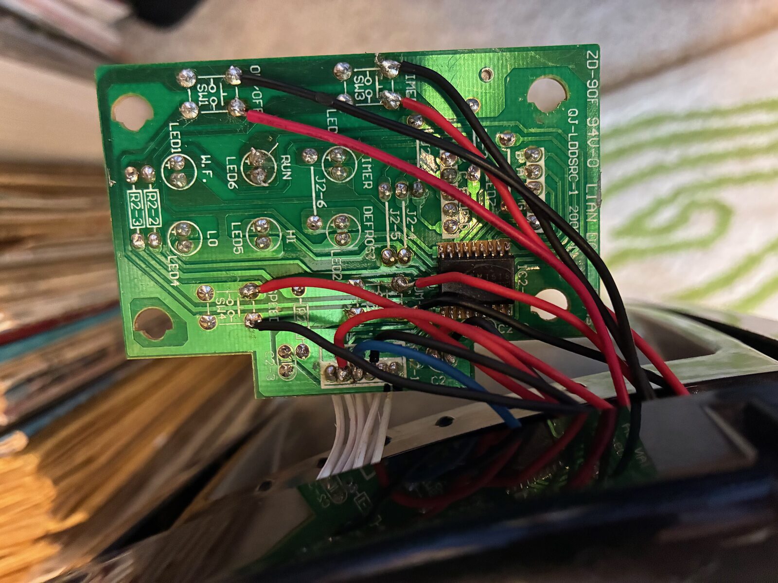
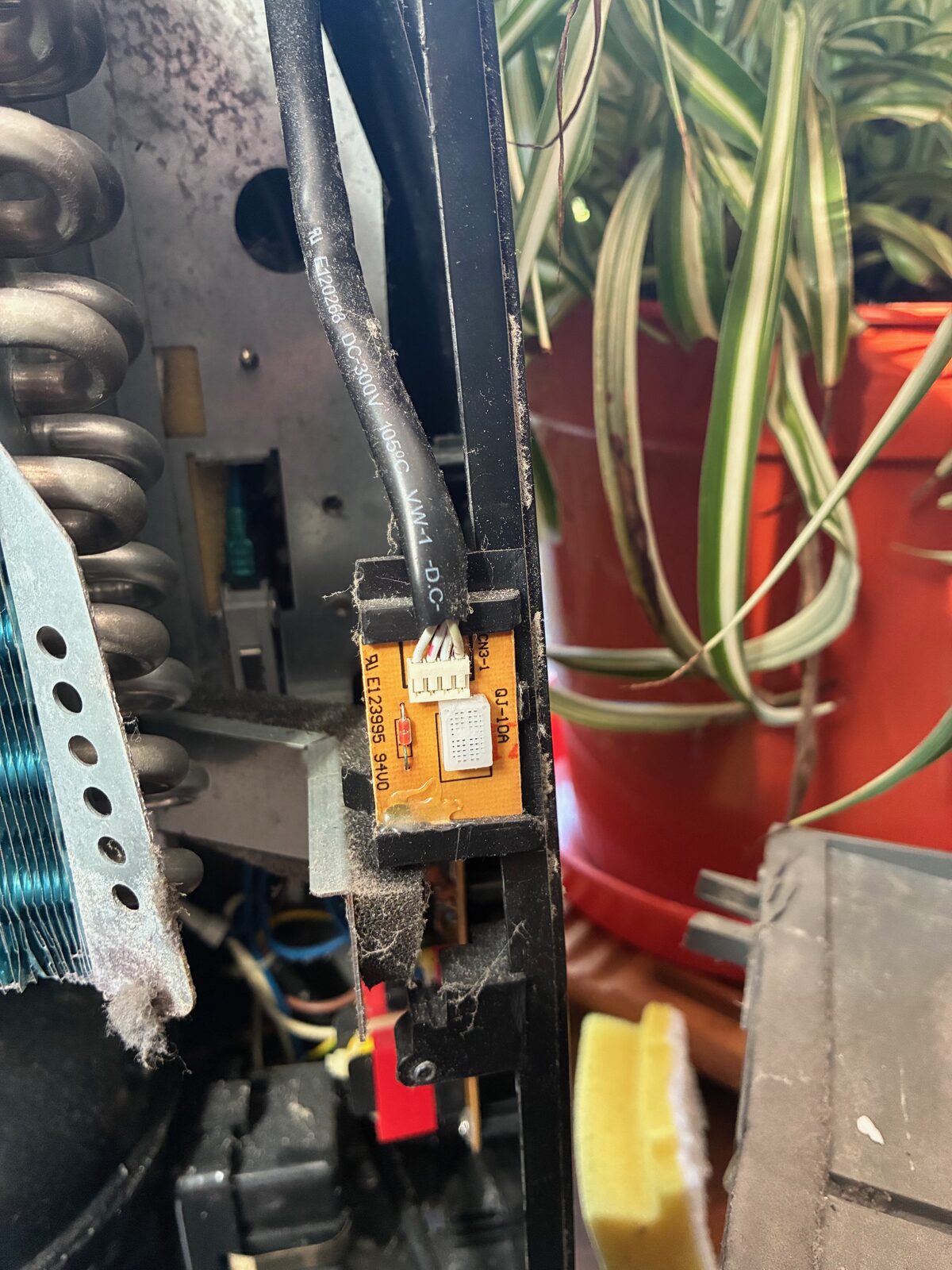
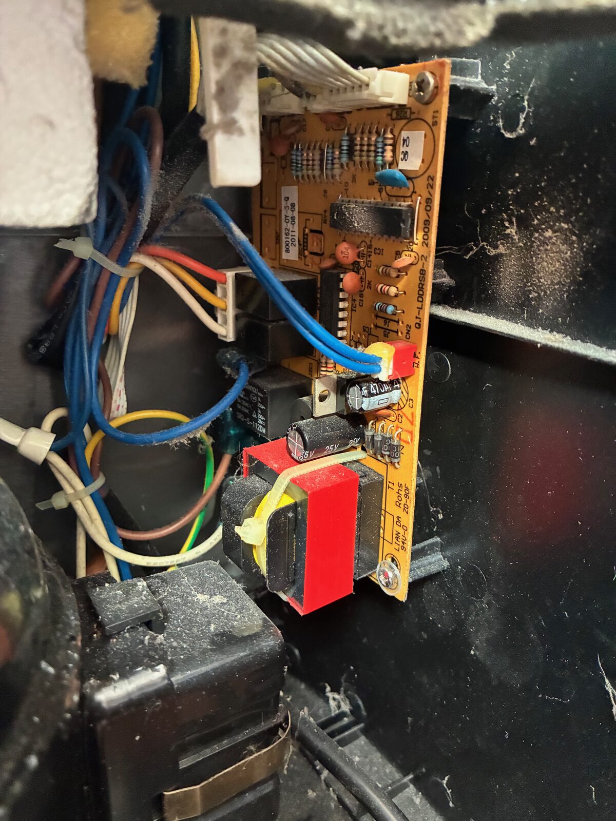
Pulling the display board revealed a tidy little PCB – a LIAN DA “LED3 DISPLAY”, dated 2009 – driven by a TM1618, an 18-pin LED-driver-plus-keyscan chip that talks to the main board over a 3-wire serial bus (CLK, DIO and a strobe/STB line). This is the good stuff: that bus carries the state of every indicator, the content of both digits, and the key-scan data for the buttons. Sniff it passively and the ESP can read everything the panel knows without me soldering to a single LED.
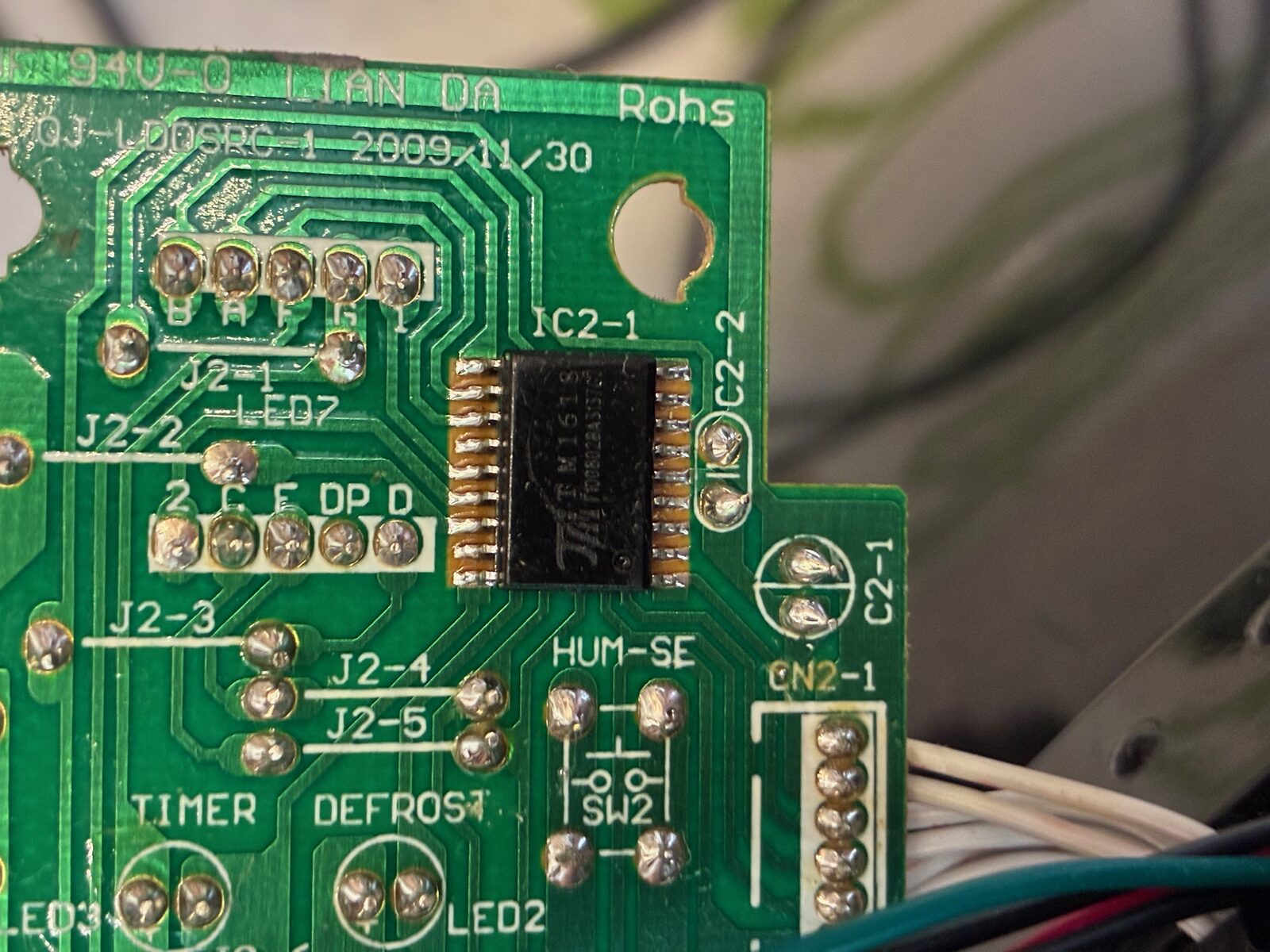
4. Tapping the bus (without letting the smoke out)
The bus arrives at the display board on the CN2-1 connector. A few minutes with a multimeter and the manual’s wiring diagram sorted out what was what: a 5 V rail, ground, and the three signal lines.
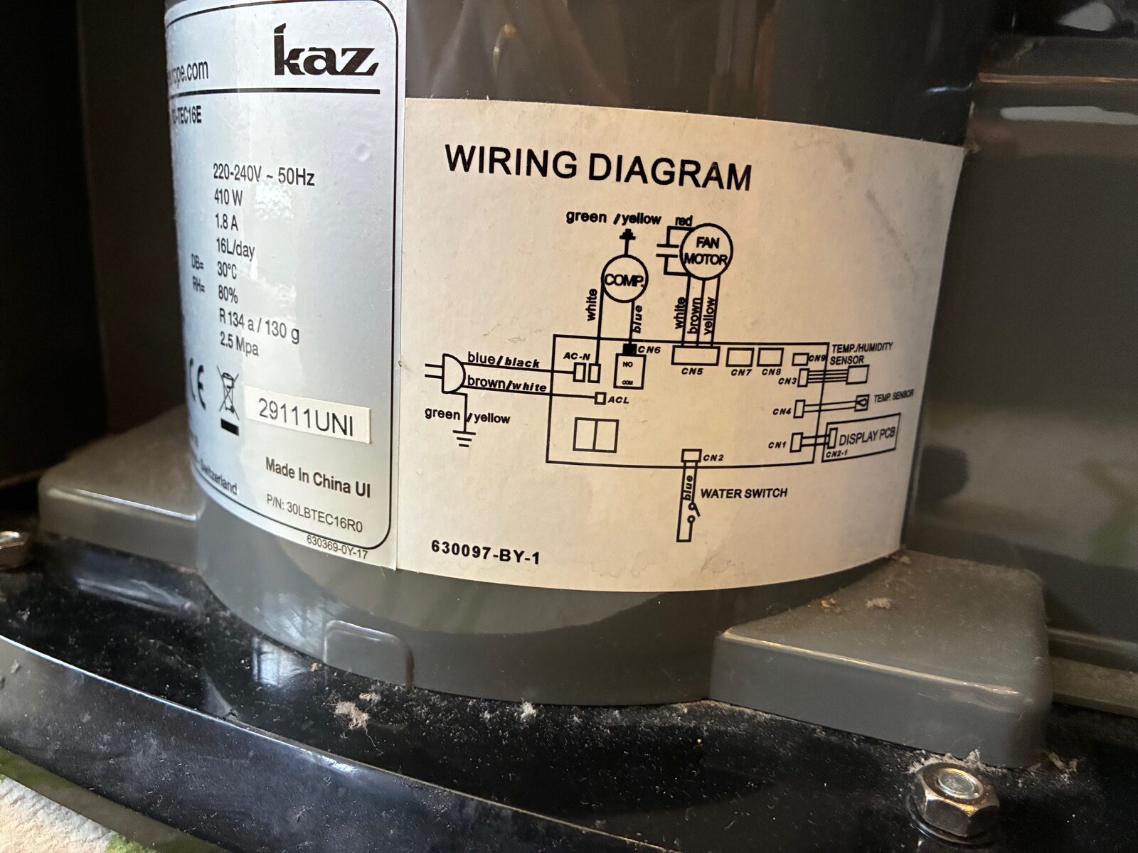
A few rules I set myself before anything got soldered, mostly learned the hard way over the years:
- The display board’s 5 V rail powers the indicator LEDs only – never the ESP. On a unit like this the logic supply can be a capacitive dropper with only milliamps to spare, and stealing from it is how you get mystery resets (or worse).
- A shared ground between display board, interface board and ESP is non-negotiable – it’s the reference the whole thing hangs off.
- Keep the signal wires short (< 25 cm), run a ground alongside them, and route well clear of the compressor wiring.
- No bare Dupont jumpers anywhere near a vibrating compressor. Proper connectors or soldered-and-heatshrinked, or you’ll be back in here in a month. (Ask me how I know.)
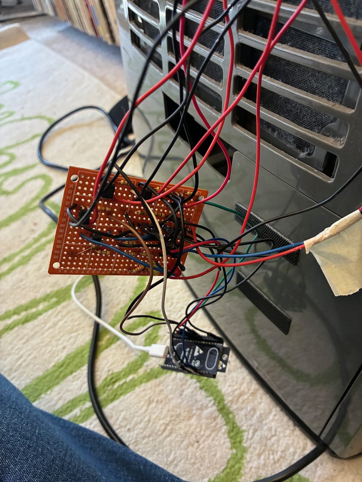
5. A little interface board
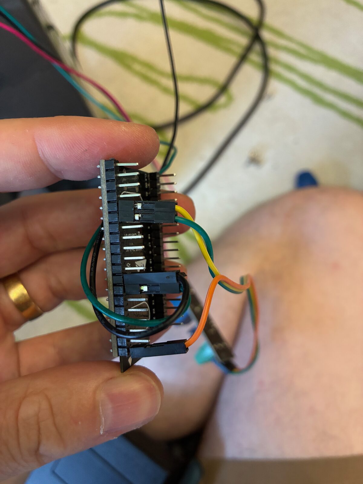
The TM1618 side runs at 5 V and the ESP32’s inputs are happier at 3.3 V, so each of the three signal lines gets a simple resistor divider on a scrap of perfboard on the way in. I ended up using three 47k resistors per line (a series 47k into two 47k to ground), which drops 5 V to a comfortable ~3.3 V – safely inside the ESP’s logic levels without loading the bus.
A word of warning if you copy this: those divider values assume a 5 V rail. If your unit’s logic runs at 3.3 V, skip the dividers entirely and wire straight through – divide a 3.3 V signal and the ESP will read nothing at all. Measure first. I also added a couple of indicator LEDs (a power light, and a “bus alive” light) because a board you can glance at and trust is worth the extra five minutes.
6. Which wire is which?
Three identical-looking signals, and I needed to know which was the clock, which the strobe and which the data line before any decoding would make sense. Rather than guess, I flashed a quick diagnostic ESPHome build with a pulse counter on each pin and simply looked at the rates:
sensor:
  - platform: pulse_counter
    pin: GPIO34
    name: "SIG1 pulses"
    update_interval: 2s
  - platform: pulse_counter
    pin: GPIO35
    name: "SIG2 pulses"
    update_interval: 2s
  - platform: pulse_counter
    pin: GPIO16
    name: "SIG3 pulses"
    update_interval: 2s
The answer fell straight out of the numbers. The display refreshes continuously at around 1,700 frames a second, which gave a clock (CLK) buzzing away at ~16–17 kHz – by far the busiest line – a strobe (STB) ticking at a steady ~1.7 kHz, and a data line (DIO) whose rate wobbled depending on what was on the display. Interestingly the CLK-to-STB ratio came out at exactly 10.0, i.e. a fixed mix of short command and longer data frames. That continuous refresh, incidentally, is also why my old multimeter only ever saw a meaningless 1–2 V average on these lines.
7. Reading the panel’s mind
With the lines identified, the next step was a small custom ESPHome component to capture each bus frame and keep a copy of the TM1618’s display RAM – then walk the unit through every state with the physical buttons and watch which bits changed. Off, on, fan low, fan high, timer, tank out, each setpoint… note the “before” and “after”, and the meaning of each bit reveals itself.
It wasn’t quite that clean the first time. Because the display is scanned, a naive capture catches whichever scan phase it happened to land on, so the low bytes flicker between values even when the panel is genuinely steady – the tell-tale sign of grid multiplexing. The fix was a firmware pass that takes a per-byte majority vote over a full scan period before deciding anything is “stable”. After that, every state change dropped out as a single clean line, and the map came together:
| Function | Where it lives |
|---|---|
| RUN (compressor / the famous LED6) | byte 2, bit 0x02 |
| Fan High | byte 3, bit 0x20 |
| Fan Low | byte 2, bit 0x01 |
| Water Full (tank) | byte 1, bit 0x10 |
| Timer active | byte 0, bit 0x04 |
| Display value (mode / setpoint) | bytes 4–7 signature |
That first row is the whole reason we’re here. After three years of fiction, the RUN state now comes straight off the bus – solid when the compressor’s actually running, and even correctly showing the little startup flash before the compressor kicks in. The tank-full state was the most satisfying capture of all: pull the tank and the entire display collapses to a single bit set, byte1 & 0x10. No ambiguity at all.
8. Pressing the buttons back
Reading is only half of it. To actually control the unit from Home Assistant I wanted to press all four panel buttons (Power, Mode/Humidity, Timer, Speed), not just the one on the old relay. These buttons aren’t simple switches – they’re read by the TM1618’s key-scan matrix – so you can’t just short them to ground. The trick is a little optocoupler (a PC817C) across each button: the ESP drives the opto’s LED, the opto’s output side bridges the two switch pads as if a finger had pressed them, and crucially it stays electrically isolated so the scan doesn’t care.
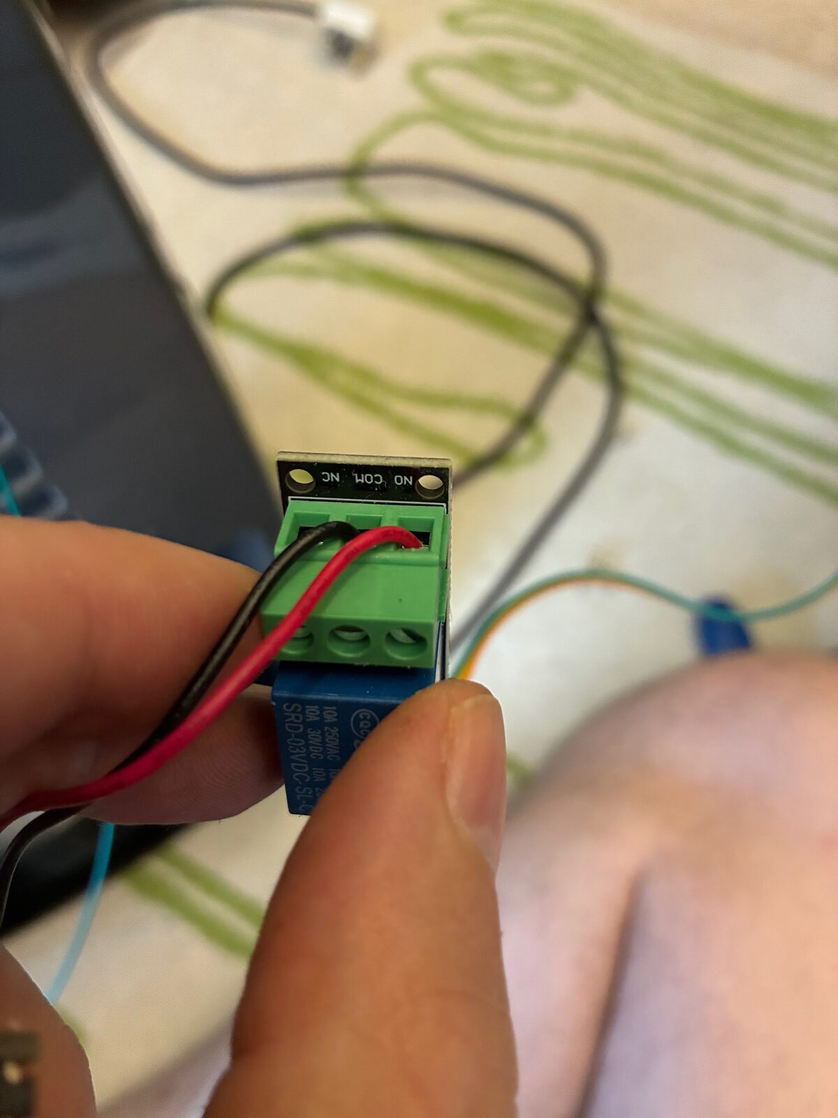
Four optos later, Home Assistant has four proper button entities, each firing a short pulse. The old relay stayed in place as a safety net until the opto approach had earned its keep, then bowed out gracefully.
9. What it looks like in Home Assistant
The payoff is a dehumidifier that’s finally honest about itself: Running, Tank Full, Fan Hi/Lo and Timer as proper binary sensors, the mode/setpoint on the display decoded to text, and four buttons for control. A couple of nice details fell out along the way:
- Closed-loop automations. The old logic ran “blind” – it pressed the button on a timer and hoped. Now the automations check the real RUN sensor and only press power if the state is actually wrong, so it can never get out of sync. It runs the unit when the tumble dryer’s going or the room creeps over a humidity threshold, and stops when it’s done or dry.
- Runtime and lifetime counters. Because RUN is now trustworthy, I get honest runtime-today / 7-day stats and a lifetime “odometer” of compressor hours.
- Bus health diagnostics. After reinstalling the unit the data went quiet one day – a CLK wire had worked loose at the display board. I’ve since added a per-line edge-rate sensor for each of the three wires, so a dead line now shows as a zero on a dashboard instead of a mystery.
One quirk worth flagging for anyone attempting the same: this panel only shows the setpoint for a few seconds after you press the Mode button, then it reverts to showing ambient humidity. So a resting glance at the display can’t be trusted as the setpoint – the firmware latches the last real setpoint it saw, and Home Assistant only believes the display for a few seconds after a Mode press. There is genuinely no way to read a setpoint the unit simply isn’t showing you.
10. Keeping an eye on it: the dashboard
With honest state finally coming off the bus, it was worth giving the dehumidifier a proper home in Home Assistant rather than a handful of stray entities. The result is a dedicated dashboard view laid out in tiles: a Status section (Running, Tank Full and the decoded mode/setpoint), Fan & Timer, a Controls block with the four button entities (Power, Mode, Speed, Timer), the Conservatory Climate readings it works against, and a Running History graph so I can see at a glance when it has actually been cycling.
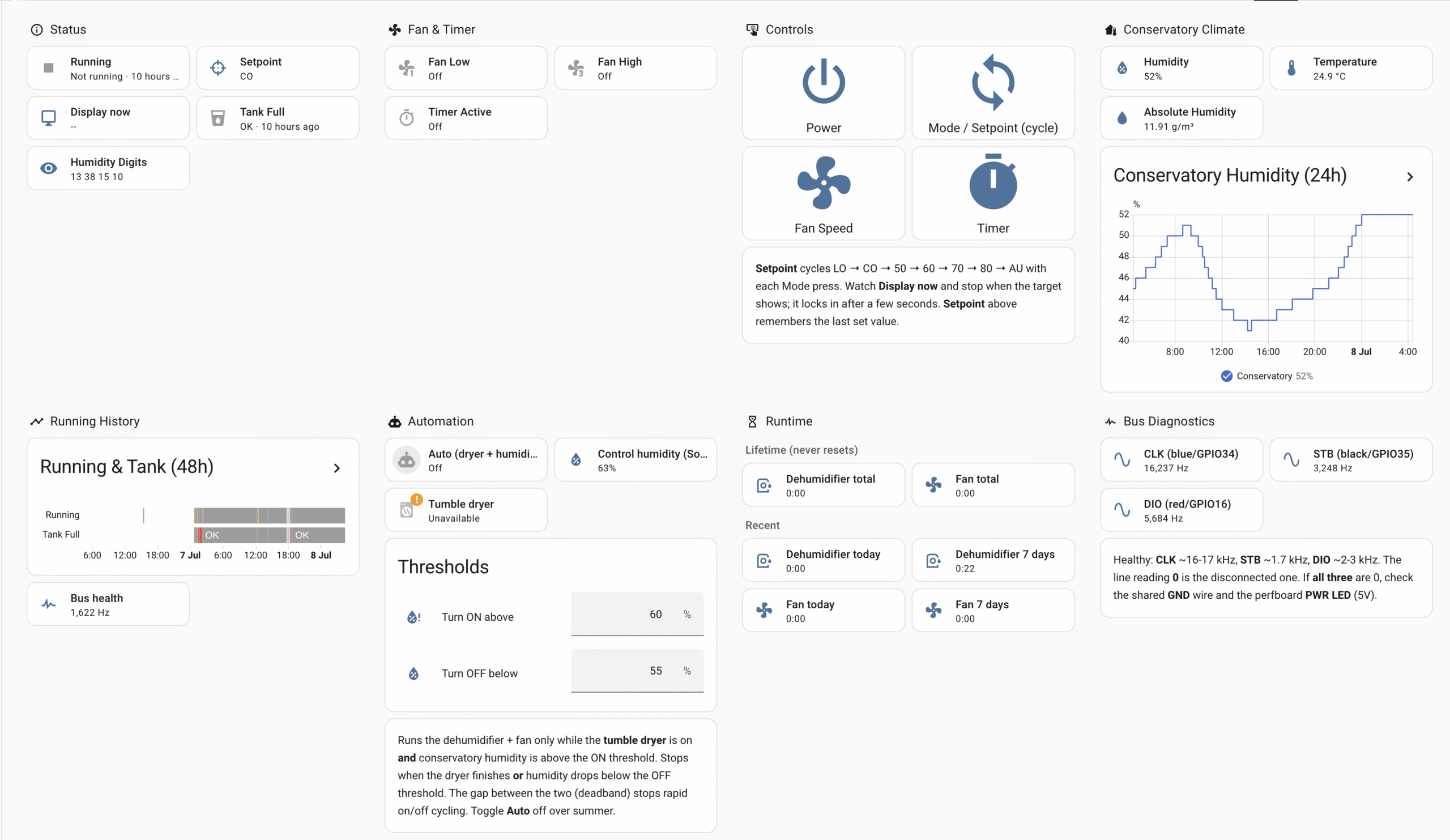
Two smaller sections earn their keep quietly. A Runtime block splits into lifetime “odometer” hours (which never reset) and recent today / 7-day totals – genuinely useful now that the runtime figure is trustworthy. And a Bus Diagnostics section shows the live edge-rate of each of the three wires (CLK, STB, DIO); the day that CLK wire worked loose, this turned a baffling silence into an obvious zero on a graph. There’s also an Automation block that surfaces the humidity on/off thresholds as sliders, so the closed-loop behaviour is tunable without diving into YAML.
11. Decisions and dead ends
In the spirit of the old build logs, here’s what didn’t make the cut, so you can skip the same wrong turns:
- ADC sensing of the panel LEDs – unworkable in principle on a multiplexed display. Every filtering strategy I tried was beaten by scan traffic that’s present in all states. This was the three-year red herring.
- Optocouplers for sniffing the bus – too slow to follow a 16 kHz clock. They’re perfect for the buttons, where speed is irrelevant, but not for reading.
- Diving into the main board – tempting, but the display bus already carries every bit of state I need at far lower risk. If I ever want ground-truth power draw, an energy-monitoring plug is the safer answer than probing mains-side.
12. Still on the list
It’s doing everything I set out to do, but a couple of odds and ends remain for a rainy day (literally):
- The Defrost lamp. I can’t force a defrost on demand, so that bit’s waiting to be captured passively on a properly cold morning.
- Decoding arbitrary humidity digits. The mode glyphs (LO, CO, 50/60/70/80, AU) are decoded, and those already seed the 7-segment map, but I need the display to sit on a range of live numbers to finish it – and this summer’s heatwave keeps the conservatory too dry for the unit to bother. A job for a damp autumn.
Not bad for a problem that sat unsolved for three years. If you’ve got one of these Kaz / Duracraft units – or any appliance with a TM1618 or similar behind the front panel – the same passive-sniffing trick is well worth a look before you start hacking at LEDs. Questions and war stories welcome in the comments.